Selecting a sprocket rarely feels like a high-stakes engineering decision. However, treating it as a simple commodity purchase ignores a harsh mechanical reality. It serves as a critical variable in system uptime. It also heavily dictates your maintenance overhead. Imprecise specification creates hidden penalties across your entire facility. You might experience premature chain elongation early in the operational cycle. Localized tooth wear often follows closely behind. Ultimately, unexpected downtime halts daily operations.
We wrote this guide to solve these exact problems. It gives engineering and procurement teams a concrete framework. You will learn how to evaluate chain fit properly. We also cover bore configurations in detail. Finally, we examine material constraints for mechanical components. This objective approach ensures you build durable drives. You avoid severe premature failures. It empowers you to specify replacement parts correctly the first time.
Key Takeaways
- Matching a roller chain sprocket requires exact alignment with regional standards (ANSI vs. ISO/BS) to prevent accelerated drive wear.
- Bore and hub configurations dictate both the maximum torque capacity and the operational downtime required for future maintenance.
- Material selection must balance environmental compliance (e.g., washdown environments) with tensile strength requirements.
- Replacing chains without replacing worn sprockets reduces the lifespan of the new chain by up to 50%.
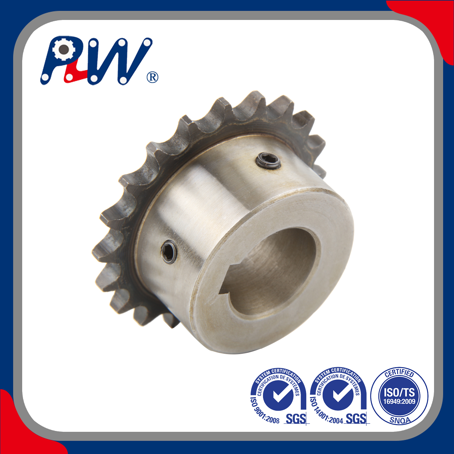
Defining Baseline Requirements for Power Transmission Sprockets
Treating parts as identical drop-in replacements often causes immediate integration failures. Standardized dimensions do not mean universally interchangeable parts. You cannot simply grab any power transmission sprocket from an industrial catalog. Misaligned operational expectations destroy mechanical drives rapidly. Every system features unique stress factors. Before reviewing manufacturer specifications, define your specific operational loads clearly.
- Continuous vs. Shock Loading: Smooth material conveyors require entirely different load profiles than heavy industrial crushers. Shock loads demand higher impact resistance.
- RPM Requirements: High-speed systems generate extreme friction and heat. They demand tighter concentricity and specific lubrication methods.
- Environmental Constraints: Corrosive washdown chemicals degrade standard metals within weeks. Determine your exposure risks early during the design phase.
The sprocket directly dictates the operational life of the entire drive system. It distributes mechanical load across multiple teeth simultaneously. Proper load distribution minimizes point stress on individual chain rollers. Improper selection concentrates massive torque onto a single tooth. This concentrated stress shears teeth quickly. It also stretches steel linkages beyond repair. You must match the component exactly to your baseline operational criteria. Ignoring this principle guarantees accelerated failure rates.
Chain Fit and Standardization: Decoding ANSI vs. ISO Specifications
Two dominant standards govern sprocket dimensions globally. You must separate ANSI protocols from ISO or British Standard (BS) rules. They look nearly identical to the naked eye. However, their internal geometries clash severely.
The American National Standards Institute governs most North American drives. Understanding an ANSI sprocket requires decoding its specific numbering system. A #40, #50, or #80 designation follows a strict internal logic. The first digit represents pitch in 1/8-inch increments. Therefore, a #40 means a 4/8-inch (or 1/2-inch) pitch. An #80 indicates a full 1-inch pitch. The second digit denotes the roller type. A zero indicates a standard roller proportion. A five indicates a rollerless bushing design.
ISO and British Standards use specific metric equivalents. Mixing standard chains with metric sprockets causes immediate mechanical binding. The mismatch creates severe frictional drag during rotation. Ultimately, the drive suffers catastrophic failure under load.
You must evaluate three critical dimensions during your selection process:
- Pitch: The exact distance measured between roller centers.
- Roller Constraints: The specific outer diameter and width of the mating roller.
- Tooth Profile: The root diameter tolerances governing how deeply the roller seats.
Physical verification prevents catastrophic ordering errors. Do not guess dimensions based on visual wear patterns. Worn metals distort your visual perception. Instead, use precision digital calipers. Measure the exact pitch across three consecutive pins on your existing chain. Verify the internal roller width carefully. Compare these physical measurements against engineering catalogs. Do this before specifying any replacement component.
Common Mistakes During Verification
Always clean the chain thoroughly before measuring. Grease and debris add false thickness to roller diameters. Measure in multiple spots. Average your findings to account for uneven stretching across the chain loop.
Hub and Bore Configurations: Balancing Installation Speed and Torque
The physical footprint of your drive dictates the hub categorization. You must define this spatial footprint before machining begins. Manufacturers divide these into three distinct categories.
- Type A (Plate): This style features absolutely no hub. You typically weld it directly to a shaft or mount it via flat flanges.
- Type B (Hub on one side): This design fits standard industrial applications. It sits flush against machinery walls, saving lateral space.
- Type C (Hub on both sides): High-load applications require this robust design. It maximizes shaft contact area to handle extreme torque safely.
Bore mounting solutions dictate installation speed. They also determine your future maintenance efforts. Different environments require distinctly different mounting strategies.
Comparison of Bore Mounting Solutions | Bore Type | Upfront Setup Requirement | Maintenance Speed | Best Application Scenario |
| Plain / Rough Stock Bore | Minimal | Slow (Requires machine shop intervention) | Custom in-house fabrications managing tolerances tightly. |
| Finished Bore | Moderate | Moderate | Standard predictable shaft sizes utilizing standard keyways and setscrews. |
| Bushed Bores (Taper-Lock & QD) | Higher | Fastest | Heavy applications requiring quick removal without galling precision shafts. |
Plain bores carry high operational risk if your machine shop manages tolerances poorly. Finished bores offer excellent pre-machined convenience. However, bushed bores represent the engineering ideal for high-torque systems. They utilize tapered bushings to grip the shaft tightly. They reduce maintenance downtime significantly. You can swap them quickly without galling or damaging precision shafts. We highly recommend them for heavy-duty applications. They provide exceptional clamping force around the entire shaft circumference.
Material Selection: Durability vs. Environmental Constraints
Compare materials based on operational realities rather than generalized marketing claims. Every environment tests a standard sprocket differently. You must map specific material features directly to your desired outcomes.
Carbon steel serves as the baseline industrial choice. It performs exceptionally well in dry, non-corrosive environments. It balances simple machinability with reliable tensile strength.
However, carbon steel fails rapidly under severe shock loads. In these cases, you need specially hardened teeth. Manufacturers use induction or case-hardening processes to strengthen the metal surface. This process extends wear life significantly. Hardened teeth are absolutely essential for any roller chain sprocket possessing fewer than 25 teeth. Small diameters undergo frequent chain engagements. They generate more heat. The hardening process resists these abrasive conditions effectively.
Food processing presents entirely different mechanical challenges. Washdown environments demand strict regulatory compliance. Harsh chemicals destroy carbon steel quickly. Here, a stainless steel sprocket becomes mandatory. It resists highly corrosive chemical exposure safely. However, you must observe a critical engineering caveat. Stainless steel offers lower maximum tensile strength compared to hardened carbon steel. It also exhibits lower wear resistance over long periods. You must adjust your load calculations accordingly to prevent sudden fracturing.
Non-metallic or plastic variants offer specific niche benefits. They reduce overall system weight dramatically. They operate very quietly. They require absolutely no manual lubrication. But their limitations remain incredibly strict. Use them exclusively for low-torque, fractional horsepower applications. They will shatter immediately under heavy industrial loads.
Implementation Risks and Installation Realities
Installation errors destroy even the highest-quality components. Adhering to strict engineering consensus saves thousands of operational hours.
The "Replace Both" rule remains fundamentally non-negotiable. Mating a brand-new chain with a worn component causes disastrous outcomes. The new chain rapidly stretches beyond its design limits. The pins and bushings wear down instantly. The chain physically alters itself to match the worn pitch of the old teeth. This dangerous practice reduces the lifespan of the new chain by up to 50%.
Alignment tolerances require absolute precision. A perfectly selected industrial sprocket will fail rapidly if misaligned. Misalignment by even a fraction of a degree causes severe damage. It drastically increases side-plate wear. Drive noise escalates immediately upon startup. Use laser alignment tools. They ensure perfect coplanar operation between the driving and driven shafts. Do not rely on simple string lines or straight edges.
Lubrication dependencies dictate operational success. Material choice and operating speeds determine your lubrication requirements explicitly.
- Drip Lubrication: Sufficient for low-speed drives operating in relatively clean environments.
- Bath Lubrication: Required for moderate speeds to ensure continuous cooling and friction reduction.
- Slinger Lubrication: Mandatory for high-speed systems to force oil directly into moving pin clearances.
Follow a strict shortlisting logic to mitigate adoption risks. Use this step-by-step summary chart to finalize your selection properly.
Shortlisting Logic Summary Chart | Step | Action Required | Primary Goal |
| 1. Determine Standard | Identify ANSI vs. ISO/BS via careful caliper measurement. | Prevent binding and ensure structural compatibility. |
| 2. Calculate Load & Teeth | Define RPM, continuous vs. shock load, and required tooth count. | Establish required baseline torque capacity accurately. |
| 3. Select Material | Match metal or plastic to environmental risks (e.g., chemical washdown). | Prevent corrosion and rapid material degradation. |
| 4. Choose Bore Type | Select plain, finished, or bushed designs based on your shaft setup. | Optimize installation speed and future maintenance access. |
Conclusion
Selecting standardized components requires balancing multiple technical variables. You must guarantee dimensional accuracy above all else. Mounting efficiency directly impacts your maintenance schedules. Furthermore, material suitability prevents environmental degradation.
Take immediate action before purchasing replacement parts. Audit your current drive system closely today. Document existing wear patterns on the metal teeth. Verify your exact shaft dimensions using digital measurement tools. Finally, consult comprehensive engineering catalogs to finalize precise part numbers. A methodical approach ensures your mechanical systems remain robust. They will operate reliably for years without unexpected breakdowns.
FAQ
Q: Can I use an ANSI roller chain on an ISO standard sprocket?
A: No. The pitch and roller diameters differ fundamentally. Attempting this mismatch leads to immediate chain binding. It causes accelerated drive wear. It also creates the potential for catastrophic failure under operating load.
Q: When should I specify hardened teeth on an industrial sprocket?
A: We highly recommend hardened teeth for drive systems possessing 25 teeth or fewer. They are also mandatory for systems operating in highly abrasive environments. Drives subjected to heavy shock loading require them to prevent rapid tooth shearing.
Q: Is a stainless steel sprocket as strong as a carbon steel one?
A: No. Stainless steel provides superior corrosion resistance for washdown environments. However, it generally possesses lower surface hardness and tensile strength than heat-treated carbon steel. You must adjust your load capacity calculations downward when specifying stainless components.
Q: How do I know if my sprocket needs replacing?
A: Look closely at the tooth profile. Hooked or "shark fin" shaped teeth indicate severe wear. Deepened tooth roots also signal imminent failure. Finally, check if you can pull the chain significantly away from the teeth at the 3 o'clock position.

 Español
  English
  العربية
  Français
  Русский
  Português
  Deutsch
  italiano
  日本語
日本語  한국어
한국어  Nederlands
  Tiếng Việt
  ไทย
ไทย  Polski
  Türkçe
  አማርኛ
አማርኛ  ພາສາລາວ
  ភាសាខ្មែរ
  Bahasa Melayu
  ဗမာစာ
ဗမာစာ  தமிழ்
தமிழ்  Filipino
  Bahasa Indonesia
  magyar
  Română
  Čeština
  Монгол
  қазақ
қазақ  Српски
  हिन्दी
  فارسی
فارسی  Kiswahili
  Slovenčina
  Slovenščina
  Norsk
Norsk  Svenska
  українська
  Ελληνικά
  Suomi
Suomi  Հայերեն
  עברית
עברית  Latine
  Dansk
Dansk  اردو
اردو  Shqip
Shqip  বাংলা
বাংলা  Hrvatski
  Afrikaans
  Gaeilge
  Eesti keel
  Māori
Māori  සිංහල
සිංහල  नेपाली
  Oʻzbekcha
  latviešu
  অসমীয়া
  Aymara
  Azərbaycan dili
  Bamanankan
  Euskara
  Беларуская мова
  भोजपुरी


