Have you ever wondered how helical gears are made? These gears are essential in modern mechanical systems, offering smooth and efficient power transmission. Their spiral-shaped teeth make them quieter and capable of handling higher loads compared to other gear types.
In this article, we’ll explore the manufacturing process of helical gears, from material selection to quality control. By understanding these steps, you’ll gain insights into how these gears maintain performance and reliability in various industries.
1. Understanding Helical Gears and Their Importance in Machinery
What is a Helical Gear?
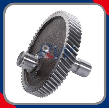
A helical gear is a cylindrical gear with teeth that are cut at an angle to the gear's axis of rotation. This angled tooth design enables smooth, progressive engagement, which contrasts with the instantaneous meshing of straight-cut gears. The primary advantage of helical gears is their ability to transmit power more efficiently while reducing noise and vibrations, which is particularly important in high-speed and high-load applications. The teeth of helical gears are cut in a spiral manner, providing a larger contact area between meshing gears, resulting in smoother operation and enhanced load-carrying capabilities.
Unlike straight gears, where teeth engage abruptly, helical gears engage gradually as the teeth move in a more continuous manner. This gradual engagement reduces the shock loads during operation, leading to longer gear life and improved performance, especially in critical systems like automotive transmissions, industrial machinery, and robotic actuators.
Applications of Helical Gears
Helical gears are highly versatile and are used in a wide range of applications across various industries. Some of the most common uses include:
● Industrial Machinery: In gearboxes, conveyors, compressors, and machine tool spindles, where durability and efficiency are paramount.
● Automotive: Helical gears are commonly used in transmissions, drive axles, and engine timing systems due to their ability to handle high torque and speeds.
● General Machinery: Fans, pumps, and reducers in manufacturing and processing plants require reliable gears to ensure smooth operation.
● High-End Equipment: Helical gears are often employed in robotic joints, aerospace transmission systems, and precision machinery, where the demands for accuracy and reliability are high.
The advantages of helical gears—such as their smooth operation, ability to handle larger loads, and quieter performance—make them the go-to choice for industries that require efficient and reliable power transmission solutions.

2. Key Steps in Helical Gear Manufacturing
Step 1: Material Selection for Helical Gears
The material selection for helical gears is one of the most important factors that impact their performance. Gears must be made from materials that can withstand high stresses, heat, and wear while maintaining their integrity over time. Common materials used for manufacturing helical gears include:
● Steel: Steel alloys like 20CrMnTi (carburized and quenched) for heavy-load applications and 45# steel (quenched and tempered) for medium-load applications offer excellent strength and wear resistance.
● Cast Iron: Suitable for low-speed, light-load applications, cast iron is often used in less demanding gear systems. HT200 is a common cast iron material used in these applications.
● Non-Metallic Materials: For applications requiring low noise and lubrication-free performance, materials such as nylon or POM (Polyoxymethylene) are utilized. These materials are ideal for environments where gears are exposed to low-speed conditions and light loads.
The material selected must meet industry standards such as ISO 6336 (for gear load capacity calculation) and AGMA 2001 (American Gear Manufacturers Association standard), ensuring that the gears will perform reliably and efficiently under their operating conditions.
Step 2: Gear Design and Specifications
Once the material is chosen, the next step is the design phase. This stage is critical to ensuring that the gear will function optimally in its intended application. The design process involves several key steps, including:
● CAD (Computer-Aided Design): Engineers use CAD software to create detailed, three-dimensional models of the helical gears. This software allows for precise control over the dimensions and tooth profile of the gears, ensuring that they meet the specific performance requirements.
● Key Design Parameters:Module (m): This defines the size of the gear and determines its load-carrying capacity. The standard module size ranges from 1 mm to 20 mm, depending on the application.
○ Pressure Angle (α): This affects the smoothness of meshing and the efficiency of power transmission. The standard pressure angle is 20°, but a lower angle (14.5°) can be used to reduce noise in specific applications.
○ Helix Angle (β): The angle between the tooth line and the gear axis determines how much axial load the gear can handle. A larger helix angle increases the gear's load capacity but also generates greater axial forces, which must be managed using thrust bearings.
○ Number of Teeth (z): The total number of teeth on the gear directly affects the gear ratio and overall performance. A typical range is between 12 and 60 teeth.
Using these parameters, engineers ensure that the gears will operate at maximum efficiency and fit into the machinery or system they are intended for.
3. The Helical Gear Cutting Process
Understanding Gear Cutting Techniques
The process of cutting helical gears involves several methods, each of which is chosen based on the complexity of the gear design and the desired level of precision. The most common gear cutting techniques include:
● Hobbing: This is the most commonly used method for cutting helical gears. It involves a rotating cutting tool called a hob, which cuts the teeth into the gear blank progressively. Hobbing is fast and efficient, making it ideal for large-scale production.
● Shaping: In this process, a reciprocating cutting tool moves back and forth to form the gear teeth. Shaping is generally used for smaller batches or gears with complex tooth profiles.
● Milling: This method uses a rotating cutter to remove material and form the gear teeth. Milling is typically used for gears that require high precision or have very specific design features.
Gear Teeth Cutting in Detail
The teeth of helical gears are cut at an angle, usually between 8° and 20° to the axis of rotation. This angular cut allows for smooth engagement of the teeth, resulting in quieter operation and a higher load capacity. The teeth gradually mesh as the gears rotate, reducing shock loading and providing a continuous transfer of power. The precision of this process is vital, as even minor inaccuracies in the teeth profile can lead to uneven wear and reduced gear performance.
Machines Used for Helical Gear Cutting
Several machines are used to produce helical gears with high precision:
● CNC Machines: Computer Numerical Control (CNC) machines offer the highest level of precision. These machines are capable of cutting helical gears with tight tolerances, ensuring that the teeth profiles and angles are consistent.
● Gear Hobbing Machines: These machines are specifically designed for gear cutting and are widely used in the production of helical gears. They use a rotating hob to progressively cut the teeth into the gear blank.
These machines allow manufacturers to produce gears with the required accuracy and consistency, ensuring smooth operation and reliable performance.
4. Heat Treatment for Strength and Durability
The Role of Heat Treatment in Helical Gear Manufacturing
Heat treatment is essential for enhancing the strength and durability of helical gears. Through processes such as carburizing, nitriding, and quenching, manufacturers can improve the hardness and wear resistance of the gear material, allowing the gears to withstand higher loads and longer operational lifespans.
● Carburizing: This heat treatment process involves adding carbon to the surface of the gear, which hardens the outer layer and improves wear resistance. This method is commonly used for heavy-duty gears.
● Nitriding: Nitriding involves infusing nitrogen into the gear's surface, making it more resistant to wear and corrosion. It is particularly useful for gears that will be exposed to harsh environments.
● Quenching: Quenching is the rapid cooling of the heated gear to harden it. This process increases the gear's strength, allowing it to handle higher stresses without failure.
These heat treatments ensure that the gears maintain their structural integrity under heavy loads, extending their lifespan and improving their performance.
5. Quality Control in Helical Gear Production
Measuring Precision in Helical Gears
To ensure the helical gears meet the required standards, manufacturers use a variety of measuring tools to check their precision:
Tool Type | Purpose |
Micrometers | Measure the gear's diameter and thickness |
Tooth Profile Gauges | Ensure the tooth profiles are accurately formed |
CMM (Coordinate Measuring Machine) | Checks the gear’s overall dimensions and tolerances |
These tools are used to verify that the gear's dimensions, tooth profiles, and angles are within the specified tolerances. Even slight deviations can lead to performance issues, such as uneven wear or noise during operation.
Ensuring Gear Accuracy
Accurate tooth alignment and surface finish are critical for ensuring the gear operates smoothly. Manufacturers also use tooth alignment checks and surface finish measurements to ensure the gear meshes correctly with its counterpart and minimizes friction.
6. Advanced Manufacturing Techniques for Helical Gears
Additive Manufacturing (3D Printing) in Gear Production
Additive manufacturing, or 3D printing, is an emerging technology that is being used to prototype complex gear designs or produce small batches of gears. 3D printing allows for the creation of gears with intricate geometries that would be difficult or impossible to achieve with traditional manufacturing methods. While it is not yet widely used for mass production, additive manufacturing shows promise for developing gears with reduced weight or for applications that require high customization.
The Role of Automation in Gear Manufacturing
Automation plays a crucial role in the modern production of helical gears. Automated machines are capable of performing repetitive tasks with minimal human intervention, reducing the risk of errors and improving production speed. Automation also ensures consistent quality across large production runs, which is essential for industries where reliability and precision are paramount.
7. The Importance of Lubrication and Surface Finishing in Helical Gears
Lubrication for Helical Gears
Lubrication is essential for minimizing friction between meshing gears. In high-load applications, such as automotive transmissions or industrial machinery, proper lubrication reduces wear, prevents overheating, and prolongs the life of the gears. Special gear oils and greases are often used to ensure smooth operation and to reduce friction between the teeth during operation.
Surface Finishing Techniques
After the gears are cut, surface finishing techniques like polishing and grinding are used to refine the surface and enhance gear performance. These processes help to reduce friction and improve the smoothness of gear meshing, ensuring efficient power transmission and minimizing noise and wear.
Conclusion
At Hangzhou Perpetual Machinery & Equipment Co., Ltd., we specialize in manufacturing high-performance helical gears by focusing on precise material selection, gear design, heat treatment, and strict quality control. Adhering to international standards like ISO 6336 and AGMA 2001, our gears are engineered for reliable performance in high-load, high-speed applications. With the right materials and advanced manufacturing techniques, our helical gears provide long-lasting durability and efficiency, making them ideal for industrial, automotive, and advanced technology systems. We ensure that our gears remain a cornerstone of modern mechanical design, offering exceptional reliability even in the most demanding environments.
FAQ
Q: What is a helical gear?
A: A helical gear is a type of cylindrical gear with spiral-shaped teeth that engage gradually, providing smooth and efficient power transmission. They are widely used in high-load and high-speed applications due to their ability to reduce noise and vibrations.
Q: How are helical gears manufactured?
A: Helical gears are manufactured through processes like material selection, gear design, cutting (e.g., hobbing or milling), heat treatment, and quality control. These steps ensure the gears meet performance standards for applications in industrial machinery, automotive, and more.
Q: Why are helical gears preferred over spur gears?
A: Helical gears offer smoother engagement and less noise compared to spur gears. Their spiral teeth provide progressive contact, which reduces impact loads, making them ideal for high-load, high-speed applications.
Q: What materials are used for manufacturing helical gears?
A: Common materials for helical gear production include steel alloys (like 20CrMnTi for heavy loads), cast iron (for lighter applications), and non-metallic materials like nylon for low-noise, lubrication-free environments.
Q: What are the advantages of using helical gears?
A: The primary advantages of helical gears include smoother operation, lower noise, higher load capacity, and the ability to transmit power efficiently in various industrial, automotive, and technological applications.
 Español
  English
  العربية
  Français
  Русский
  Português
  Deutsch
  italiano
  日本語
日本語  한국어
한국어  Nederlands
  Tiếng Việt
  ไทย
ไทย  Polski
  Türkçe
  አማርኛ
አማርኛ  ພາສາລາວ
  ភាសាខ្មែរ
  Bahasa Melayu
  ဗမာစာ
ဗမာစာ  தமிழ்
தமிழ்  Filipino
  Bahasa Indonesia
  magyar
  Română
  Čeština
  Монгол
  қазақ
қазақ  Српски
  हिन्दी
  فارسی
فارسی  Kiswahili
  Slovenčina
  Slovenščina
  Norsk
Norsk  Svenska
  українська
  Ελληνικά
  Suomi
Suomi  Հայերեն
  עברית
עברית  Latine
  Dansk
Dansk  اردو
اردو  Shqip
Shqip  বাংলা
বাংলা  Hrvatski
  Afrikaans
  Gaeilge
  Eesti keel
  Māori
Māori  සිංහල
සිංහල  नेपाली
  Oʻzbekcha
  latviešu
  অসমীয়া
  Aymara
  Azərbaycan dili
  Bamanankan
  Euskara
  Беларуская мова
  भोजपुरी


