Selecting the wrong sprocket configuration does not just cause minor operational inefficiency. It often leads to accelerated chain wear, systemic vibration, and catastrophic drive failure. Systemic vibration specifically triggers chordal action within the mechanical assembly. This action damages expensive bearings and compromises overall structural integrity. You cannot afford to guess when specifying these critical power transmission components.
Precision in mechanical systems requires perfectly aligning three essential engineering specifications. You must accurately determine the pitch, tooth count, and bore size. You must match these exact parameters to the specific load, speed, and spatial constraints of your application. Overlooking even one dimensional requirement guarantees poor equipment performance and unplanned factory downtime.
We will provide an engineering-grounded framework for evaluating a standard roller chain sprocket. Procurement and maintenance teams will learn to specify replacement parts correctly. You will discover how to maximize system uptime and ensure highly reliable torque transfer. Following this practical guide ensures precision in every industrial drive system upgrade.
Key Takeaways
- Pitch dictates capacity: The chain pitch determines the sprocket's baseline load capability and must strictly match the ANSI chain standard.
- Tooth count drives performance: Modifying sprocket pitch tooth count directly alters the speed-to-torque ratio and influences the smoothness of the drive.
- Minimum tooth thresholds matter: Falling below 15-17 teeth exponentially increases wear due to excessive articulation angles.
- Bore sizing requires hub compatibility: Bore dimensions must account for shaft fit (clearance vs. interference) and the appropriate hub classification (Type A, B, or C).
The Foundation of Standard Roller Chain Sprockets: Pitch Defined
Precision engineering always starts by defining the core sprocket pitch accurately. We define sprocket pitch as the precise linear distance between the centers of two adjacent chain rollers. It acts as the primary mathematical foundation for any mechanical drive setup. You must measure this distance exactly to ensure smooth chain engagement. An inaccurate pitch measurement ruins drive synchronization entirely.
Industry standardization strictly dictates how we classify these transmission components globally. Organizations like the American National Standards Institute (ANSI) and the International Organization for Standardization (ISO) govern these exact physical dimensions. For example, a #40 standard chain always features a 1/2-inch pitch distance. A #50 chain utilizes a 5/8-inch pitch. A #60 chain requires a 3/4-inch pitch. Strict compliance ensures seamless interchangeability across different manufacturing environments. You cannot mix different standard components without risking immediate catastrophic failure.
Engineers must evaluate pitch size against specific physical load requirements carefully. Pitch directly correlates to the maximum mechanical load capacity of the entire system.
- Larger pitch configurations: These setups provide much higher baseline tensile strength. They handle immense mechanical load capacities safely. However, they inherently support a much lower maximum RPM. They generate significantly more noise and vibration at higher operational speeds.
- Smaller pitch configurations: These profiles deliver exceptionally smoother operation. They allow for much higher rotational speeds safely. They reduce harmful chordal action significantly. However, they offer a vastly reduced tolerance for heavy, sudden shock loads.
You must balance these two engineering extremes based on your unique application demands. Always consider operational speed and peak torque ratings before finalizing your specific pitch selection.
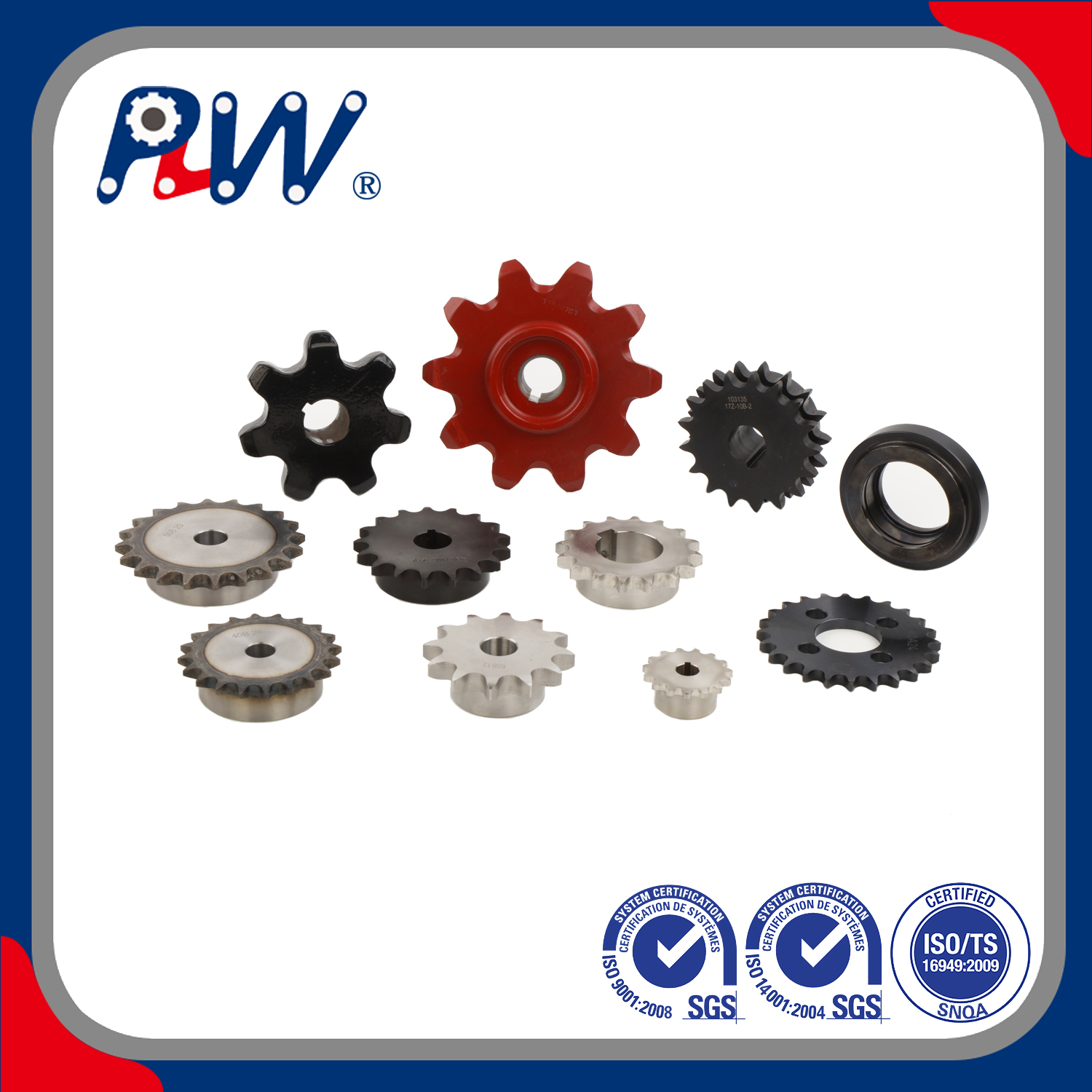
How Sprocket Pitch Tooth Count Dictates Speed and Torque
Every mechanical drive system relies heavily on a fundamental inverse relationship between speed and torque. The standard gear ratio formula governs this precise mechanical interaction. You change machine performance characteristics dramatically simply by altering the tooth count on your installed sprockets. When rotational output speed increases, available output torque inherently decreases. When you demand higher lifting torque, you must sacrifice rotational speed.
You must clearly distinguish between driving and driven sprockets during evaluation. The driving sprocket attaches directly to the electrical motor or primary power source. The driven sprocket connects directly to the mechanical load.
- Increasing driven tooth count: Adding teeth on the driven unit multiplies the output torque safely. This modification simultaneously decreases the final output rotational speed. It serves perfectly for heavy-lifting hoist applications.
- Decreasing driven tooth count: Removing teeth on the driven unit increases the final output speed. However, it severely sacrifices available pulling torque. This approach works best for high-speed material conveyor lines.
Altering an existing system requires strict decision-stage consideration. Engineers cannot simply swap standard components arbitrarily. You must recalculate the shaft center distance carefully. You must verify the new sprocket pitch tooth count does not exceed your physical spatial footprint. Adding teeth expands the Outside Diameter (OD) significantly. This sudden expansion frequently causes severe physical interference with existing safety guards or structural machine frames.
Table 1: Impact of Driven Sprocket Adjustments on Drive Performance
| Driven Sprocket Modification | Impact on Output Speed | Impact on Output Torque | Common Application Scenario |
| Increase Total Tooth Count | Significantly Decreases | Significantly Increases | Lifting heavy structural loads, industrial hoists |
| Decrease Total Tooth Count | Significantly Increases | Significantly Decreases | Fast packaging lines, high-speed conveyors |
The Hidden Threat to Chain Life: Chordal Action and Tooth Count Limits
Mechanical designers frequently battle a destructive phenomenon known generally as chordal action. We commonly define this issue as the "polygonal effect" in power transmission circuits. It describes the vertical rise and fall of the chain as it engages the sprocket teeth. Because sprockets act mechanically as polygons rather than perfect circles, the chain experiences constant pulsation. This unavoidable rhythmic pulsation creates intense systemic vibration. It accelerates metal fatigue across all moving parts over time. It forces vital lubricants out of the chain pin joints prematurely.
Standard engineering practice relies on strict rules of thumb to combat chordal action effectively. You should maintain a minimum of 17 teeth for any high-speed drive systems. Keeping the tooth count above 17 significantly minimizes the vertical chain lift during rotation. It keeps the linear chain speed much more consistent. It protects the drive shaft bearings from unnecessary harmonic pounding.
You must also observe a hard absolute limit for tooth counts. Avoid dropping below 15 teeth unless tight space constraints make it physically impossible. Falling below 15 teeth exponentially increases the severe articulation angles of the individual chain links. This extreme bending angle destroys chain rollers rapidly. It requires operators to accept a drastically reduced overall system life. It generates excessive operational noise and destructive harmonic vibrations.
Engineers also leverage the "hunting tooth" principle to extend component longevity naturally. You should pair an odd number of teeth (like 21T or 25T) with an even number of chain pitches. This simple mathematical offset ensures each tooth engages a completely different chain link during every rotation cycle. It distributes the inevitable mechanical wear evenly across all sprocket teeth. It prevents localized metal deterioration and maximizes your preventative maintenance intervals safely.
Specifying Bore Size, Hub Types, and Mounting Mechanics
Selecting the correct bore size involves observing strict mechanical mounting realities. The central bore must match your drive shaft diameter precisely. However, the selection process goes far beyond a single caliper measurement. It requires choosing the right secure mounting mechanism to handle the specific torque profile of your application. You must manage shaft fit tolerances properly. A loose clearance fit causes damaging fretting. A heavy interference fit requires specialized thermal expansion techniques for proper mounting.
Understanding common hub classifications prevents serious industrial procurement errors. Industry nomenclature categorizes hubs into three primary types based on physical extensions.
- Type A (Flat): These units contain no hub extension whatsoever. They remain completely flat on both sides. Manufacturers usually weld or bolt them directly to existing flanges or separate hub assemblies securely.
- Type B (Single Hub): These sprockets feature an extended hub on exactly one side. This critical extension provides essential stability along the mounting shaft. It allows for highly secure set screw or keyway installation.
- Type C (Double Hub): These units feature extensions on both sides symmetrically. They offer absolute maximum shaft support. Engineers specify them strictly for exceptionally heavy loads or massive pitch diameters.
Evaluating mounting solutions requires a structured decision matrix. You must match the exact mounting style to your operational environment.
- Finished Bore (Plain/Keyway): These components arrive completely ready to install. They feature precise set screws and standard cut keyways. They work perfectly for standard, predictable shaft sizes and moderate torque applications.
- Taper-Lock / QD Bushings: These mechanisms provide vastly superior clamping force for extreme high-torque applications. They compress tightly onto the shaft. This creates incredibly secure friction clamping. It guarantees much easier removal later without damaging fretting corrosion.
- Minimum Plain Bore (MPB): These feature a very small, rough pilot bore. They remain ideal when you require custom machining capabilities in-house. You can bore them out to exact, non-standard specifications easily.
Step-by-Step Evaluation Framework for Sprocket Replacement
Replacing worn components demands a highly methodical engineering approach. Following a rigid step-by-step evaluation framework eliminates dangerous guesswork and prevents costly system failures. Do not skip any physical measurement phases during this evaluation.
Step 1: Verify the Chain Standard.
You must always start by measuring the existing chain setup carefully. Measure the exact pitch distance and the internal roller diameter. You should use precision digital calipers to verify these dimensions. This guarantees the new replacement sprocket matches the specific ANSI or ISO rating perfectly. A mismatched standard causes immediate mechanical binding and rapid catastrophic drive failure.
Step 2: Calculate Required Speed/Torque.
You must establish a firm operational baseline first. Count the teeth on both the driving and driven sprockets to baseline current performance. Document the existing gear ratio meticulously. Before making any adjustments for new operational requirements, verify your exact sprocket pitch tooth count. Recalculate your output speeds and center distances carefully if you plan to upgrade the current machine setup.
Step 3: Measure Spatial Constraints.
Physical limitations dictate many critical engineering choices. Calculate the exact Pitch Diameter (PD) and Outside Diameter (OD) of the proposed replacement part. The OD determines the absolute maximum physical footprint. You must ensure the new, potentially larger sprocket will successfully clear all safety guards, machine framing, and adjacent rotating components.
Step 4: Confirm Shaft Specs.
Take highly accurate measurements of the designated mounting shaft. Measure the shaft diameter and the keyway width using reliable digital tools. Determine the optimal hub classification (Type A, B, or C). Select the most robust bushing mechanism for your specific environmental conditions. Specify stainless steel components or specialized protective coatings for highly corrosive washdown areas.
Conclusion
Optimizing industrial power transmission requires treating pitch, tooth count, and bore size as a fully interconnected mechanical system. You cannot evaluate these parameters as isolated, independent dimensions. Altering one physical variable inherently shifts the performance outcomes of the others. Pitch dictates overall structural strength. Tooth count determines operational speed and torque output. Bore size guarantees secure mechanical power transfer from the motor.
We strongly advise you to consult comprehensive engineering sizing charts. Contact dedicated application engineers to verify exact torque ratings and safe center distances before finalizing your procurement shortlists. Take photographs of existing wear patterns to identify latent misalignment issues early. Proper planning and precise measurement secure maximum equipment uptime. They ensure your mechanical drives operate flawlessly under the most demanding industrial conditions.
FAQ
Q: How do I measure the pitch of a heavily worn sprocket?
A: You should use precision digital calipers to measure the exact linear distance between the centers of two adjacent tooth valleys. If the teeth display severe metal wear, measuring the sprocket directly becomes unreliable. In this case, measure the pitch of the existing drive chain itself. Measure across three consecutive chain rivets, divide by two, and you will determine the true pitch accurately.
Q: Can I use a metric chain on an ANSI standard sprocket?
A: No. You must never mix metric and ANSI standards under any circumstances. They feature distinctly different mathematical pitch measurements and internal roller diameters. Attempting to force a metric chain onto an ANSI standard sprocket causes severe binding. The mismatch creates excessive friction, damages the rollers immediately, and leads to rapid catastrophic drive failure.
Q: Why is my drive chain vibrating excessively at low speeds?
A: Excessive low-speed vibration almost always points directly back to a low tooth count on your installed sprockets. Using fewer than 15 teeth creates severe chordal action, or vertical chain pulsation. This polygonal effect forces the chain to rise and fall dramatically during engagement. Improper chain tension or severe wear elongation also exacerbates this violent shaking effect.
Q: Does sprocket diameter strictly depend on tooth count?
A: Yes. For any given fixed pitch size, adding more teeth inherently increases both the pitch diameter and the outside diameter. The physical relationship remains mathematically absolute. You cannot increase the total tooth count without expanding the physical footprint of the component. You must verify adequate spatial clearance before upgrading to higher tooth counts.

 Español
  English
  العربية
  Français
  Русский
  Português
  Deutsch
  italiano
  日本語
日本語  한국어
한국어  Nederlands
  Tiếng Việt
  ไทย
ไทย  Polski
  Türkçe
  አማርኛ
አማርኛ  ພາສາລາວ
  ភាសាខ្មែរ
  Bahasa Melayu
  ဗမာစာ
ဗမာစာ  தமிழ்
தமிழ்  Filipino
  Bahasa Indonesia
  magyar
  Română
  Čeština
  Монгол
  қазақ
қазақ  Српски
  हिन्दी
  فارسی
فارسی  Kiswahili
  Slovenčina
  Slovenščina
  Norsk
Norsk  Svenska
  українська
  Ελληνικά
  Suomi
Suomi  Հայերեն
  עברית
עברית  Latine
  Dansk
Dansk  اردو
اردو  Shqip
Shqip  বাংলা
বাংলা  Hrvatski
  Afrikaans
  Gaeilge
  Eesti keel
  Māori
Māori  සිංහල
සිංහල  नेपाली
  Oʻzbekcha
  latviešu
  অসমীয়া
  Aymara
  Azərbaycan dili
  Bamanankan
  Euskara
  Беларуская мова
  भोजपुरी


