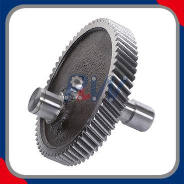
Wear-Resistant Alloy Steel Helical Gear
Precision-Engineered Helical Gear for Heavy-Duty Industrial Power Transmission
Our Wear-Resistant Alloy Steel Helical Gears are engineered for demanding industrial power transmission applications where high load capacity, tooth surface durability, dimensional stability and reliable meshing performance are essential.
Manufactured from selected alloy steels and processed through controlled gear cutting, heat treatment and precision finishing, these helical gears are designed to deliver stable torque transmission and long-term service performance in industrial gearboxes, speed reducers, machinery and automated drive systems.
The helical tooth configuration provides progressive tooth engagement and continuous load transfer between mating gears, supporting smooth operation and reducing transmission impact when the gear pair is correctly designed, lubricated and aligned.
Product Highlights
Wear-Resistant Alloy Steel Construction
Precision Helical Tooth Geometry
High Tooth-Root and Tooth-Flank Strength
Excellent Resistance to Surface Wear
Heat-Treated for Enhanced Durability
Stable Dimensional Accuracy
Controlled Profile and Helix Accuracy
Smooth and Reliable Power Transmission
Custom Gear Geometry Available
OEM Manufacturing to Approved Drawings
Inspection According to Applicable International Standards
Technical Specifications
| Parameter | Specification / Available Options |
| Product Type | Industrial Helical Gear |
| Gear Type | External Helical Gear / Internal Helical Gear |
| Application | Industrial Power Transmission |
| Material | Alloy Steel / Case-Hardening Steel / Customized |
| Typical Material Options | 20MnCr5 / 18CrNiMo7-6 / 20CrMnTi / AISI 8620 / AISI 9310 / Customer-Specified |
| Manufacturing Process | CNC Hobbing / Shaping / Milling / Grinding |
| Heat Treatment | Carburizing & Quenching / Carbonitriding / Induction Hardening / Quench & Temper |
| Tooth Surface | Hardened / Ground / Finished According to Specification |
| Surface Hardness | According to Material and Heat-Treatment Specification |
| Effective Case Depth | According to Gear Size and Engineering Requirements |
| Module | According to Gear Design |
| Number of Teeth | Customer Specification |
| Gear Ratio | Customer Specification |
| Pressure Angle | According to Gear Design |
| Helix Angle | According to Gear Design |
| Helix Direction | Left-Hand / Right-Hand |
| Pitch Diameter | According to Gear Geometry |
| Outside Diameter | According to Drawing |
| Root Diameter | According to Gear Geometry |
| Face Width | According to Gear Design |
| Bore Diameter | Customer Specification |
| Keyway | Optional |
| Spline | Optional |
| Backlash | According to Gear Pair Requirements |
| Gear Accuracy | ISO / DIN / AGMA / Customer Specification |
| Tooth Profile Accuracy | According to Approved Drawing |
| Helix / Lead Accuracy | According to Approved Drawing |
| Radial Runout | According to Drawing / Inspection Plan |
| Surface Finish | Machined / Shaved / Ground |
| Inspection | Dimensional / Tooth Geometry / Runout / Hardness / Surface Inspection |
| Production | Prototype / Small Batch / Mass Production |
| Customization | OEM / ODM / Drawing-Based Manufacturing |
Engineering Note: The parameters above represent available manufacturing configurations rather than fixed specifications for every product. Final dimensions, material grade, heat treatment, hardness, accuracy class and finishing requirements are determined by the approved drawing and technical specification.
Alloy Steel Construction
The material of a helical gear directly affects its resistance to tooth wear, contact fatigue and tooth-root loading.
Depending on the application, alloy steel options can be selected according to:
Typical material options may include 20MnCr5, 18CrNiMo7-6, 20CrMnTi, AISI 8620 and AISI 9310, subject to the customer's engineering specification.
For demanding applications, case-hardening steels can be selected to provide a hard and wear-resistant tooth surface while maintaining a tougher supporting core.
The final material grade should always be confirmed according to the actual gear design and application requirements.
Wear-Resistant Tooth Surface
Gear wear is affected by the combined influence of material, heat treatment, surface finish, lubrication, load and operating conditions.
Our helical gears can be manufactured with heat-treatment processes such as:
Carburizing & Quenching
Provides a hardened surface layer with a tough supporting core and is widely used for demanding transmission gears.
Carbonitriding
Used for selected gear applications where a controlled hardened surface and appropriate core properties are required.
Induction Hardening
Provides localized surface hardening where the gear material and geometry are suitable for the process.
Quench & Temper
Provides a balanced combination of strength and toughness for applications where deep case hardening is not required.
Final surface hardness and effective case depth should be specified according to the material, gear dimensions, loading conditions and approved heat-treatment process.
Precision Helical Gear Geometry
Helical gears are characterized by teeth arranged at a defined helix angle relative to the gear axis.
During operation, the angled tooth surfaces engage progressively rather than entering full contact simultaneously. This geometry can provide smooth load transfer and stable rotational movement.
Key design parameters include:
Normal module
Number of teeth
Pressure angle
Helix angle
Helix direction
Pitch diameter
Base diameter
Outside diameter
Root diameter
Face width
Tooth thickness
Backlash
Profile modification
Lead modification
For a properly designed gear pair, these parameters must work together with shaft alignment, lubrication, gear accuracy and operating load.
Gear Accuracy and International Standards
For precision helical gears, international standards provide a common technical reference for manufacturing and conformity assessment.
ISO 1328-1:2013 establishes the ISO flank tolerance classification system for individual cylindrical involute gears. It covers tolerance-related parameters including single pitch deviation, cumulative pitch deviation, profile deviation, helix deviation and runout-related evaluation. The standard defines eleven flank tolerance classes, numbered 1 to 11 in increasing order of tolerance.
Applicable gear requirements can therefore be specified according to:
The appropriate accuracy class should be selected according to the actual transmission requirements rather than using a generic “high precision” claim.
Load Capacity and Gear Performance
For heavy-duty applications, gear performance must consider both tooth-root bending strength and tooth-flank surface durability.
ISO 6336-1:2019 establishes basic principles and general influence factors for calculating the load capacity of spur and helical cylindrical gears. The ISO 6336 series addresses failure modes including pitting, tooth-root breakage, tooth-flank fracture, scuffing and micropitting.
Actual gear performance depends on factors including:
Transmitted torque
Rotational speed
Gear ratio
Tooth geometry
Material
Heat treatment
Gear accuracy
Surface finish
Lubrication
Shaft alignment
Backlash
Operating temperature
Duty cycle
The ISO 6336 calculation methods are engineering evaluation tools and should not be interpreted as a guarantee of assembled gearbox performance.
Precision Manufacturing Process
1. Material Preparation
Alloy steel is prepared according to the specified material grade and purchasing requirements.
2. Gear Blank Machining
CNC turning and machining establish the required blank dimensions, bore, face width and reference surfaces.
3. Helical Tooth Cutting
The gear teeth are generated using appropriate gear-cutting processes such as CNC hobbing, shaping or milling.
4. Heat Treatment
The gear undergoes the specified carburizing, carbonitriding, induction hardening or quench-and-temper process.
5. Tooth Finishing
Depending on the required accuracy and application, tooth flanks can be finished through shaving, grinding or other specified processes.
6. Final Inspection
Critical dimensions, tooth geometry, runout, hardness and other customer-specified characteristics are verified before shipment.
Gear Inspection & Quality Control
| Inspection Item | Quality Control Focus |
| Tooth Profile | Profile deviation |
| Helix / Lead | Helix deviation and lead accuracy |
| Single Pitch | Individual pitch deviation |
| Cumulative Pitch | Cumulative pitch deviation |
| Radial Runout | Gear rotational accuracy |
| Tooth Thickness | Tooth thickness and backlash |
| Over Pins / Balls | Tooth thickness verification where applicable |
| Bore Diameter | Shaft fit |
| Bore Concentricity | Gear-to-bore alignment |
| Face Runout | Axial dimensional accuracy |
| Outside Diameter | Dimensional verification |
| Face Width | Dimensional verification |
| Surface Roughness | Tooth-flank surface condition |
| Surface Hardness | Heat-treatment verification |
| Case Depth | Hardened-layer verification |
| Material | Material grade / certification |
| Heat Treatment | Hardness and process verification |
| Final Dimensions | Drawing-based inspection |
Applications
Wear-resistant alloy steel helical gears are suitable for:
Industrial Gearboxes
Speed Reducers
Conveyor Drive Systems
Material Handling Equipment
Machine Tools
Packaging Machinery
Textile Machinery
Automated Production Equipment
Agricultural Machinery
Construction Equipment
Industrial Pumps
Heavy-Duty Mechanical Drives
Customized Transmission Systems
OEM Custom Helical Gear Manufacturing
We manufacture custom helical gears according to:
Available customization includes:
Quality Assurance
A controlled quality program can include:
Raw material verification
Gear blank inspection
CNC machining inspection
Tooth profile measurement
Helix measurement
Pitch inspection
Runout measurement
Heat-treatment verification
Surface hardness testing
Case-depth testing
Bore and concentricity inspection
Tooth surface inspection
Final dimensional inspection
Batch traceability
Customer-specific inspection reports
Why Choose Our Alloy Steel Helical Gears?
High Wear Resistance
Alloy steel and appropriate heat treatment provide a robust foundation for demanding gear applications.
Precision Tooth Geometry
Critical tooth profile, helix, pitch and runout requirements can be controlled according to the approved specification.
International Standard Reference
Gear manufacturing and inspection can be performed with reference to applicable ISO, DIN, AGMA and customer-specific requirements.
Custom Engineering
Gear geometry, materials, heat treatment and finishing processes can be configured according to the actual transmission system.
OEM Manufacturing
Suitable for prototype development, replacement gears, small-batch production and long-term OEM supply.
Request a Custom Helical Gear Quote
Send us your 2D drawing, 3D CAD model, gear data sheet or existing sample.
Our engineering team can evaluate your requirements for:
Material → Gear Geometry → Heat Treatment → Gear Accuracy → Surface Finish → Inspection
and provide a customized manufacturing solution for your industrial power transmission application.

 Español
  English
  العربية
  Français
  Русский
  Português
  Deutsch
  italiano
  日本語
日本語  한국어
한국어  Nederlands
  Tiếng Việt
  ไทย
ไทย  Polski
  Türkçe
  አማርኛ
አማርኛ  ພາສາລາວ
  ភាសាខ្មែរ
  Bahasa Melayu
  ဗမာစာ
ဗမာစာ  தமிழ்
தமிழ்  Filipino
  Bahasa Indonesia
  magyar
  Română
  Čeština
  Монгол
  қазақ
қазақ  Српски
  हिन्दी
  فارسی
فارسی  Kiswahili
  Slovenčina
  Slovenščina
  Norsk
Norsk  Svenska
  українська
  Ελληνικά
  Suomi
Suomi  Հայերեն
  עברית
עברית  Latine
  Dansk
Dansk  اردو
اردو  Shqip
Shqip  বাংলা
বাংলা  Hrvatski
  Afrikaans
  Gaeilge
  Eesti keel
  Māori
Māori  සිංහල
සිංහල  नेपाली
  Oʻzbekcha
  latviešu
  অসমীয়া
  Aymara
  Azərbaycan dili
  Bamanankan
  Euskara
  Беларуская мова
  भोजपुरी